
research interests
- Simulation environment for distributed control design based on IEC61499
- New design approaches aim to ease the design process
- Link between MATLAB Simulink and Function
Block models through:
- Standard communication channel such as UDP and TCP sockets
- Complete model transformation between two models
current projects
Model Transformation Approach from Simulink to Function Block models
Model transformation follows a block-to-block transformation approach that converts Simulink models to Function Block models. The model transformation aims to help in design by saving time and cost in designing new system in Function Block domain while there are various models have been originally built in Simulink. Since MATLAB Simulink is popular tool in the Control Industry, having such a model transformation tool may potentially improve industrial's acceptance to the Function Blocks. Also the tool introduces the simulation and data analysis functionality to the Function Block domain by bridging the link with Simulink. This immediately helps in solving the well-known complexity issues with distributed control design (i.e. IEC61499 Function Blocks designs).
The model transformation considers the aspects such as:
- Execution semantics of models
- Descretization issues
- Events handling
- Data type mapping
This approach has been tested with the following two examples:
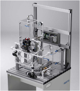
Example 1: A Two-tank System
This two-tank system is simply designed to maintain the water level of one of the tank at a specific level. The pump follows a PID control logic to fill the empty tank with water, while a valve on the top feeds the excess water back to the other tank.
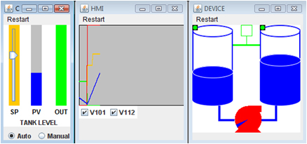
A simple system built in Simulink is transformed into a Function Block model. After adding some visualisation Function Blocks, the following simulation can be performed (in FBDK):
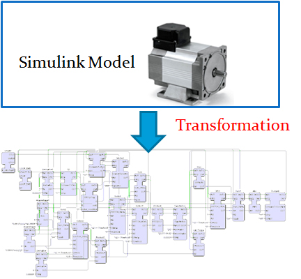
Example 2: A motor example
An industrial motor Simulink model was tested with the model transformation tool we developed. It is successfully transformed into a Function Block model and is compared the output results with the original Simulink model. The simulation results from the two models gives nearly identical output. The slight difference is due to the discretization process and a simple modelling techniques are implemented at the Function Block side (especially to blocks that involves timing issues such as integration, differentiation etc).
- Socket communication channel approach between MATLAB Simulink and Function Block models.
- Model Transformation Tool from Function Block to Simulink
- Simulation through socket communication
- Two-tank system Simulation
- The MathWorks - MATLAB and Simulink for Technical Computing
- 4DIAC
- nxtControl
- HOLOBLOC FBDK
- FBDK Google Group
- The University of Auckland
- CHIA-HAN, Y. & VYATKIN, V. (2008) Design and validation of distributed control with decentralized intelligence in process industries: A survey. 6th IEEE International Conference on Industrial Informatics, 2008. INDIN 2008, p1395-1400. Daejeon, Korea.
- VYATKIN, V., HANISCH, H. M., CHENG, P. & CHIA-HAN, Y. (2009) Closed-Loop Modeling in Future Automation System Engineering and Validation. IEEE Transactions on Systems, Man, and Cybernetics, Part C: Applications and Reviews, Vol. 39, p17-28.
- CHIA-HAN, Y. & VYATKIN, V. (2009) Automated Model Transformation between MATLAB Simulink/Stateflow and Function Blocks. IFAC INCOM 2009. Moscow, Russia.
- CHIA-HAN, Y. & VYATKIN, V. (2010) Model Transformation between MATLAB Simulink and Function Blocks. 8th IEEE International Conference on Industrial Informatics, 2010. INDIN 2010, Osaka, Japan.